Sheltering Sewers from the Rain

Pacific Northwest community optimizes its vacuum sewer system with cutting-edge telemetry monitoring

Full Article Click here

Making the switch from a purely septic-based wastewater handling model to a publicly owned and operated vacuum sewer system solved problems for the small community of Miles Crossing, Oregon. It also brought unforeseen inflow and infiltration issues.

Rain events revealed the need for tracking down operational overload issues in the system, which could only effectively be accomplished via automation tools. Retrofitting a monitoring system has given the district’s operators a real-time view of their system, potential sources of I&I, and a means to protect the mechanical health of this key community infrastructure investment.

Below sea level

The Miles Crossing Sanitary District is fairly new, incorporated when the community decided to shift from private septic systems to a public sewer system. The decision to convert the community — home to a population of approximately 800 — was based upon several factors:

 The town’s topography — situated on Youngs Bay, between the Youngs River and the Lewis and Clark River, is completely flat with elevation from 1 to 10 feet below sea level.

 Dikes are situated between properties to prevent them from going underwater during high tide or rain events.

 The high-water table was causing the area to experience a rapidly rising number of septic system failures, affecting groundwater quality.

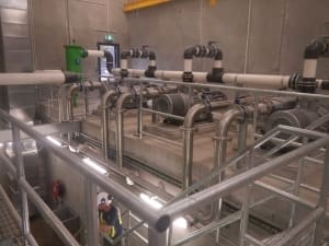
The district opted for an vacuum sewer system versus a traditional gravity system. The latter would not have been feasible due to the depths required for installation combined with high-water table levels. The vacuum system implementation process, which cost the community approximately $4 million, began in 2000 and was fully in service by 2010. It comprises 372 gravity pit connections (323 of these being residential), and a single pump station that receives the entire flow from 7.25 miles of vacuum mainline. From the pump station, two 75 hp pumps move the effluent 1.75 miles under Youngs Bay to the town of  Astoria, Oregon, for treatment.

Not quite right

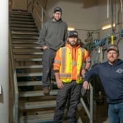
On normal, dry days, Miles Crossing would pump an average of 36,000 gallons per day; but during rain events, that would jump dramatically, sometimes by more than 150,000 gallons. Unlike a traditional system where I&I can exist between joints, cracks in manholes or other conveyance structures, a vacuum system is closed. Brandon Smith, pump station operator, and Carl Gifford, superintendent for the Miles Crossing Sanitary Sewer District, suspected stormwater was entering the system.

“One of the biggest challenges with a system like this is that not only do we not want the stormwater — the system simply cannot handle it indefinitely — but since we don’t handle our own treatment, we were sending extra effluent to Astoria that created extra costs,” Smith says. “Our job became finding out where that excess water was entering the system, and then correcting it.”

Gifford and Smith learned that when the system was put in place, contractors had taken each line that was tied into the property’s existing septic, severed it, and then tied it into the new vacuum system. On many properties, storm drains and gutters, as well as other forms of outside drainage, had been run into the septic system. The impact of bringing all these lines into the new vacuum system — instead of just the sanitary line — was unknown to the contractors.

These extra tie-ins created an unnecessary burden on the system and the pump station operations, so they needed to be located and removed. The task of finding the sources of these I&I culprits was labor-intensive and slow, so the district began looking for a technology solution that would assist in this discovery process.

Trial and error

As a first attempt, Gifford and Smith utilized individual pit-fire counters. Each time an individual property’s vacuum pit fired, it would trigger an analog or digital display to track the number of firings. This method proved expensive and unreliable as a measurement or pinpointing technique. As they continued to research other solutions, they were contacted by FLOVAC.

FLOVAC had been well established globally in the field of successful vacuum sewer system installations and was seeking connections in the North American market. It was able to offer Miles Crossing a telemetry system that could be connected to each vacuum pit and would deliver the detailed data the district needed to help pinpoint and mitigate its I&I issue.

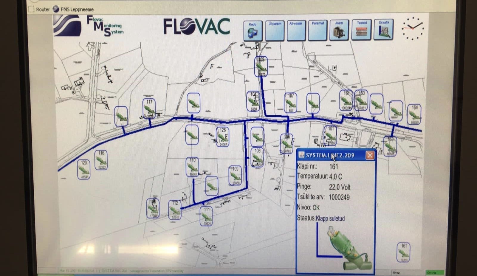
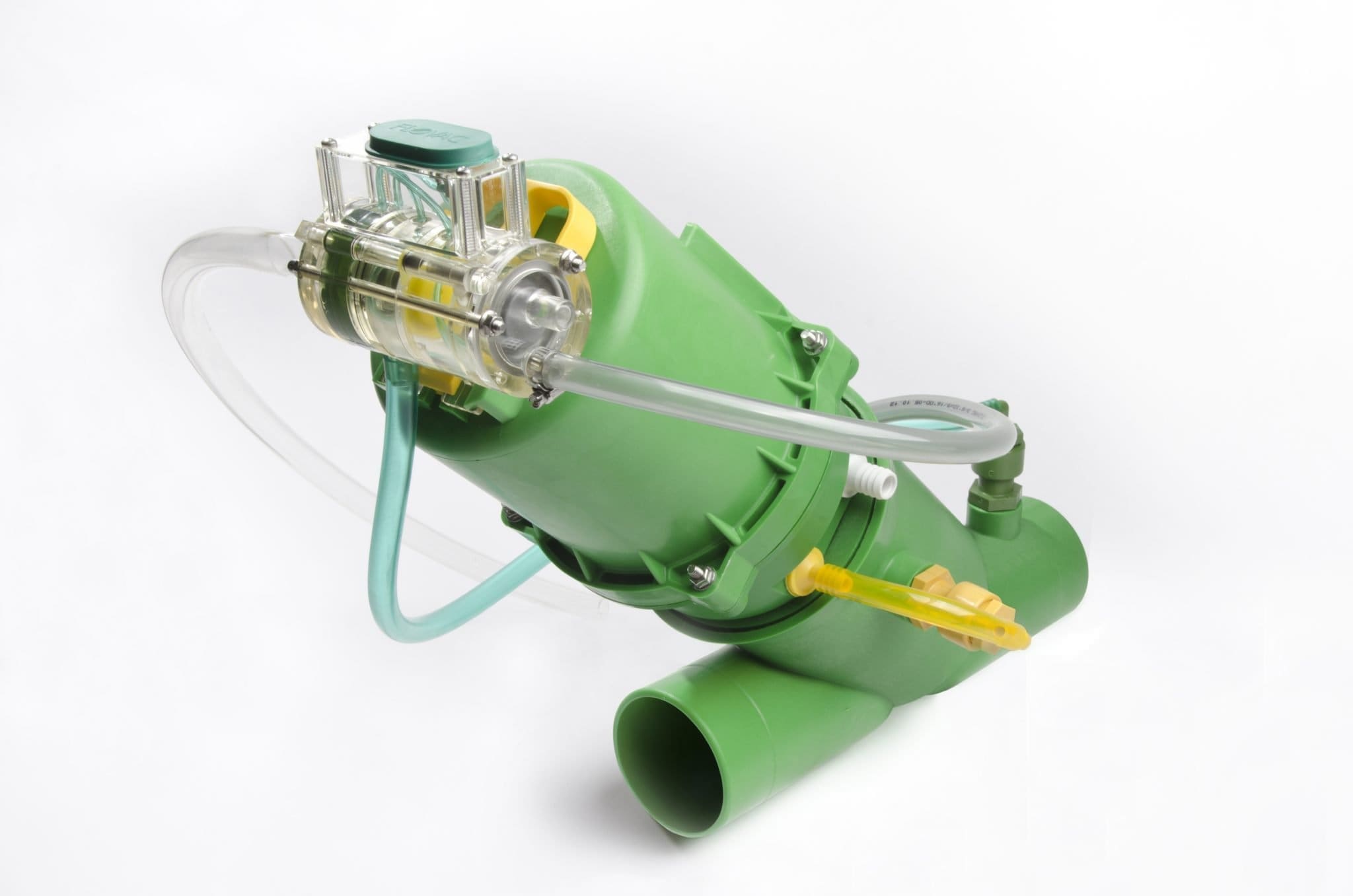
Each vacuum interface valve or connection has a magnet located inside of the top section of the valve body. The FLOVAC monitoring system works by attaching a special sensor to the valve body to detect the movement of this magnet. It detects each time the valve opens and closes, as well as how long each valve stays open.

Numbers tell all

As vacuum valves tend to fire when 10 gallons of effluent have entered the sump, the volume of flows can be calculated from the number of activations. When an unusually high volume of water enters the sump, the valve will take in a larger quantity of fluid during that one cycle. The district could detect such occurrences by how long the valve stayed open. Depending on how many properties are connected to a single collection pit, they would be able to narrow down the point of infiltration to a small area.

Related: Flood Affected Sewer Systems

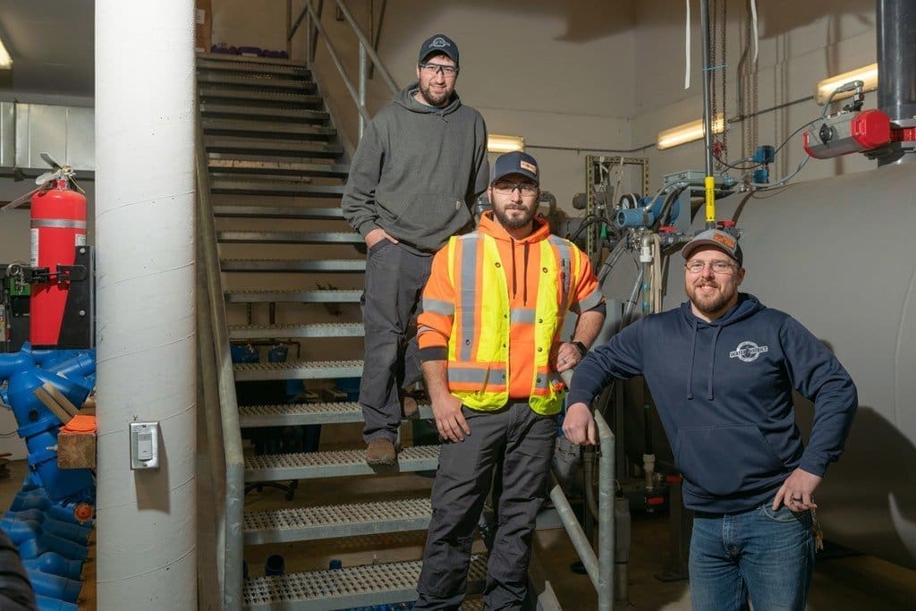
With the installation of the FMS, monitoring and telemetry data now lets operators see what the entire system is doing in real time. It allows them to view individual homes and their pits, and provides information on how many times it has fired, and when.

“This is especially helpful during a rain event,” Smith says. “We can see average trends for a property. For example, if a home that normally fires 30 times a day during a weather event starts showing 5,000 fires instead, we know there’s a problem and can deploy immediately to the property while the rain event is still happening to see exactly what’s taking place.”

One big discovery uncovered by monitoring involved a property with a partially collapsed lateral. Although it was functioning sufficiently to serve the home, it had been crushed in some areas. Where it ran from the home under the rock driveway, it was acting like a natural storm drain, pulling water straight from the surface into the sewer system pit. Using CCTV push cameras to inspect and document the line’s condition, the utility team was able to show the property owner the extent of the damage, its effects, and then work with them to develop a plan of action to resolve it.

Subtle adjustments

Normally, the monitoring units are connected to a transmitting antenna that sends data to the central monitoring system wirelessly. Due to the flat terrain and steel manhole covers on the pits, Miles Crossing ran conduit pipe out to a utility pedestal at the roadsides and installed the wireless telemetry equipment there. Everything works wirelessly through the latest Gateway, Bluetooth and LoRaWAN technology and is tied into the district’s SCADA system.

“We can set parameters as far as what we are asking it for, and to send us text messages when there are different alarms. This extra information is especially helpful when we are experiencing a lot of rainfall,” Smith says.

Since its installation, the system has required minimal maintenance. A yearly visual inspection of each valve pit is typically all that has been needed. Rare mishaps can occur, but — due to the very nature of the sealed system’s construction — if things happen, the pumping equipment operation and vacuum attributes make pinpointing issues quick.

Moving forward

Nearly 60{f2ac4d1e1d40dc2e2d9280a1dfa90d854b2d8c80eba743affa37fc4ce2e16def} of the system has been fitted with the telemetry monitoring system, and phase two of the project, a complete system rollout, is commencing shortly.

“By retrofitting the entire system with the FMS, we will know when there’s a problem before the homeowner does,” Gifford says. The monitoring system also provides a high-level float that can alert the operators when a pit begins to have an issue. Now Gifford and Smith can be more proactive versus reactive in keeping the system in peak operating status, while cutting down on field time and hunting down overflows.

With just a little more than half the system being monitored, the district has already seen significant savings in treatment costs, Gifford says.

“The vacuum system was a great solution for this community and now with the telemetry tools, we will have a sustainable, high-performing and affordable sanitary system for our district for generations to come.”

Related: Information about Flovacs Monitoring System

Flovac Collection Pits are Preferred by Vacuum Sewer Installers

Many Contractors find installing vacuum sewers much easier to install than traditional gravity sewers and low-pressure pumping systems.

Vacuum sewers are installed in shallow trenches and have an easy connection point at a property boundary for homeowners to connect up to. Gravity flow from a number of houses, usually between 2 and 6, depending on the flow rate from the property, flows to a collection pit.

The Collection Pit houses the vacuum valve which provides a pneumatic interface between the gravity side of the network and the vacuum, negative pressure, side of the network.

In older systems, concrete manholes were used as well as fibreglass collection pits. Both have had issues with I&I (Infiltration and Inflow) becoming an increasing problem. This has been picked up very well with Flovacs monitoring system. 

The Flovac collection pit has been designed by operators and is built under ISo conditions to a standard for collection pits using PE materials.

Have a look around one of our collection pits recently being installed in Florida.

The first and most applauded by operators is the shut-off valve for testing and service work on the pit. As Flovac is a world leader in vacuum technology, this is now the standard in many countries. The shut-off valve is an essential tool to keep your team safe.

The vacuum stub out is welded to the side of the pit, eliminating inflow to the valve pit and ensuring alignment with the valve is 100{f2ac4d1e1d40dc2e2d9280a1dfa90d854b2d8c80eba743affa37fc4ce2e16def} every time. Thus, reducing instillation errors and eliminating no-hub couplings coming off. Additionally, if the valve closes on water, creating a water hammer, all the energy is suppressed.

Flovac uses either H20 rated hinged or HDPE lids; both seal the valve pit from water getting in. Keeping the upper valve pit dry protects your valve and controller and eliminates operators from having to fish in stagnant water during serving. Additionally, the sump of the valve pit has a 30{f2ac4d1e1d40dc2e2d9280a1dfa90d854b2d8c80eba743affa37fc4ce2e16def} larger holding capacity on average, which is just one of our design philosophies to ensure adequate response time during an emergency.

Lastly, the feedback we receive from contractors includes how easy the pit is to set and connect. With many more connection points, clock position is not an issue.

Hard to believe, but the highest praise from contractors is that our valve pit has lifting lugs, a crucial must-have.

You can read more about our Collection Pit Here

1,000,000 cycles. How long should your vacuum valve last.

A vacuum interface valve is located in a collection pit usually outside of the property boundary at the side of the road. In most systems this collection pit is connected to 4 to 6 homes via a gravity pipe connection.

Although the vacuum system is designed so that the vacuum valve allows for a flow of .25 litres per second (4 gallons per minute) from the houses. There are some occasions where parts of a system may be designed for higher flows. This may come from schools, commercial areas, gravity fed or pumped flows. Our engineers are very careful about how these higher flows enter the system.

The vacuum valve is designed to activate pneumatically once 40 litres (10 gallons) enters the collection pit. This allows for a mix of air and water to enter the system with the correct air to liquid ratio so that the vacuum mains do not flood with too much liquid. In an average residential community, the vacuum valve will activate between 80 and 100 times per day. This is based on the average flow per house and the number of houses per collection pit.

Flovac Manager Georg Sarap checking the monitoring system via the touch screen at the vacuum pump station

For maintenance we recommend that certain parts in the valve and controller are replaced every 10 years or 300,000 cycles. The body itself has a design life of 50 years. European Standard EN 16932 calls for an endurance test with 250,000 cycles, as does the Australian Standard AS 4310 Details Here

Flovac has independant testing of the valve at 700,000 cycles, significantly more than required by the standards and represents 23 years of activation without failure.

We know that in a number of our systems we have some very high flow situations. With some its been due initially to infiltration which clients have since resolved. With others the system has been designed to cater for very high flows. High Flow Projects .

One Million Cycles

Monitoring screen showing over 1 million cycles

At our project at Leppneeme in Estonia our team has been watching one of our high flow valves closely. It has a Flovac cable monitoring system which can tell the operator the number of times the valve has operated (Tsuklite arv:). It can also alert the operator to any faults, tell the temperature in the pit, the power use and location. The pit is located very close to the vacuum station which makes it easier to handle very high flows. This week the valve passed its 1 million mark with number of cycles. Based on these activations it has done 34 years worth of work in just 8 years and is still going strong.

Fortunately the operator would be able to tell from the monitoring system if any parts were wearing as the open time of the valve would start to change.

Although we have other systems that have valves which have recorded over 1 million cycles as well as achieving this result on our test bench it has been great watching it tick over via our monitoring system.

Flovac Vacuum Valve and Controller

Engineered Solutions. Flovac Launches New 2 inch Vacuum Valve

Early vacuum sewerage systems are about to get a makeover thanks to the Flovac R&D team in conjunction with the Production team in The Netherlands. Clients from many parts of the world had struggled with getting reliable and easy to use vacuum valves to fit the earliest vacuum systems installed in the 1960’s and 1970’s.

Joel Lillienthal, the pioneer of modern vacuum systems granted early patents to Electrolux for the development of the vacuum sewerage industry in the early 1960’s. Those systems were developed using 2-inch (50 mm) vacuum valves as many were used for just grey water, marine applications and single house applications. Modern vacuum systems all use 3-inch or 90 mm vacuum vales and this is a requirement under most standards.

The 2-inch valves that were installed in many of those early projects used a membrane type valve and an old fashioned ball float controller, similar to what was used in old toilet cisterns. Both the membrane valve and ball float increased operational problems in these systems as did the smaller 2-inch size of the valve. As most plumbing fixtures within the house had a 3-inch clearance the vacuum valve became a choke point.

The development and use of 3-inch valves in the 1970’s reduced the rate of blockages and vast improvements to the technology in the years since have meant that vacuum sewers are the preferred alternate sewage system in many countries. Sadly most of these early vacuum sewers had corresponding size issues with smaller diameter pipes and small diameter collection pits for holding the vacuum valves. This meant that it was often impossible to replace the existing valves with modern larger ones.

Although there are still many hundreds of vacuum systems left from the sixties which are still working, they do have high operational costs and problems can be difficult to find. This has caused some anxiety around vacuum technology in area’s where these systems still exist.

2-Inch Valve Improvements

Flovac’s production team have been working for some time on developing a 2-inch valve to help out numerous clients from around the world. What clients had asked for was something that was

New Flovac 2-inch valve

very similar to our 3-inch valve.  You can read about all the benefits of the Flovac 3-inch ( 90 mm valve) here. Clients felt that it was the best valve and controller in the market and wanted as many of the same attributes as possible. What has been developed is very similar and includes the ability to unscrew the top half of the valve from the bottom without using any equipment. The controller also has a quick release key.  The internal free ball passage of the FLOVAC 2-inch interface valve is with 55 mm the biggest free ball passage in the existing market. This with the self-cleansing extra wide Y-body, results in higher efficiency and less chance of blockages.

Valve Monitoring Option

As an addition they have managed to make it compatible with either the cable or wireless monitoring systems.  A 2-inch valve is always going to be more susceptible to blockages so getting an alert when one occurs and in which valve it is occurring will cut down operational time considerably. Another very important reason for the use of monitoring with these old systems is that many suffer from infiltration from groundwater and stormwater. Some of these systems are now 50 years old, pipes and pits are cracking and breaking. Monitoring makes it possible to target specific areas for rectification, taking away the guesswork.


Grey Water Systems

The new Flovac-2 inch valve has not been developed for use in modern municipal system as only 3-inch valves should be used in residential area’s. One area that the 2-inch valve might find a market though is for when we do grey water only systems or smaller indoor systems. Grey water systems do not have solids and so there is little to no risk of blockages.

Flovac 2-inch valve with Grey Water Box

Please contact your closest Flovac office if you would like more information about the 2 inch valve. It will be on display at the worlds largest water industry expo at IFAT in Munich in May 2020.


Can the Flovac Valve and Controller work under water

Vacuum sewerage systems are often installed in areas which are prone to flooding and rising water tables. A question we are often asked is

“Can the Flovac Valve and Controller stilloperate when they are under water”

The simple answer is yes!

The writers of the British and European Standard for Vacuum Sewerage Systems EN16932-3:2018  and the stricter Australian Standard for Vacuum Valves AS 4310 required that a number of independent tests be undertaken. The Blockage test (seen here) and the Submergence test were two of the most important.

The reason is that “A submergence test is conducted to confirm that the valve can be installed in flood-prone areas”  In Annexure A.3 in the European Standard and Appendix F in the Australian standard it outlines what is required for the testing.

The USA does not have any standards for vacuum sewer systems so utilities should rely on other International standards.

The stricter Australian standard requires that the valve, controller and all fittings shall be capable of continuous operation without failure when immersed to a depth of 1,500 mm (5 feet) above the top of the valve body in water and/or floodwaters, which may contain large quantities of sediments. The European standard only requires that the valve is covered by 300 mm of water.

Flovac had independent auditors Dekra carry out all of the testing requirements covered in both standards. Dekra are one of the largest and most respected testing and certification organisations in the world, operating in 50 countries and with 45,000 employees.

The DEKRA Test procedure and P for Pass

Whenever our operations group has found a failure of a Flovac valve or controller at a project site which has been subject to flooding, in all cases it has been due to incorrect installation. Either due to hose clamps not installed or o-rings left off. In areas which are badly affected by flooding we will often install the controller in a dedicated pedestal next to the collection pit. This is not to protect the controller, which can still operate when submerged, but to allow the operator to fire the vacuum valve which might be covered by floodwater.

This video shows a Flovac valve with monitoring operating under water.

For those operators with a Flovac Monitoring System the valve can be fired remotely either via your phone or other IOT device.

If your project is subject to flooding there are a number of other protective measures which can be taken (read this article for more information)

Why are ISO Standards Important

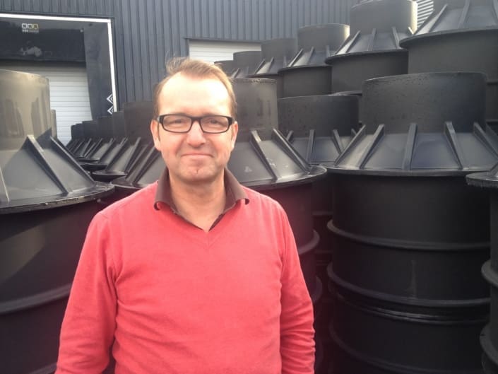
With the recent move to a new international production facility in The Netherlands, the first thing that General Manager Mr Leo Huijs had to set up was new ISO certification for the new facility.

ISO certification covers many aspects of our business and how we do the business.

ISO 9001 covers Quality and ensures that Flovac is set up to produce and deliver products to our clients in such as way as to ensure we will have every aspect of production and logistics set up to always deliver defect free product.

Our whole research and development process gets reflected within this, knowing that nothing can compromise the great efforts done by the staff in production to meet these quality standards are kept.

ISO 45001 covers our workers, to ensure that they work in a safe environment. Flovac has operated in conjunction with a sheltered workshop, working with disabled workers and so it has been upmost in Leo’s mind to make sure that all of our work processes are safe. Although the intent of ISO:45001 is in protecting our workers at the production facility we are also very mindful of the workers in the field.

Not just our own operators but our clients as well. Much thought is given to the design of our vacuum pump stations, our collection pits, our vacuum valves and our monitoring systems to ensure that at the front of our mind is the expectation that everything that we design and produce will provide a safe environment for all operators of vacuum sewerage systems.

The production facility also gets a number of visitors each year for training and education. This also includes a number of school children, coming to learn about where poop goes.

ISO 14000 is a family of standards related to environmental management that exists to help organizations minimize how their operations negatively affect the environment; comply with applicable laws, regulations, and other environmentally oriented requirements; and continually improve.

As Flovac is an environmental company and brands itself as the “Green Future of Sewerage Collection” the ISO 14001 was a very important standard for us to follow at a production level. We continually look for ways to improve our interaction and engagement with the environment.

What is the Asset Life of a Vacuum Sewer System?

As vacuum sewers are relatively new it is difficult for many engineers to develop good whole of life models when doing a comparative analysis on alternative sewer systems.

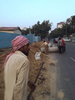
Although vacuum systems are newcomers to the sewerage industry we are seeing some systems just reaching their 50th anniversaries. Materials and designs have changed significantly since the first systems were installed in the mid sixties and although many are still operating they are nearing the end of their design life of the time.

Expectations on asset life have changed industry wide and any sewage infrastructure is expected to last significantly longer. The only national code or standard which stipulates Asset Life is the Australian WSAA Vacuum Sewerage code published in 2004. There are discussions in the WEF Alternate Sewers Guide on operational costs, but these are based on too many old systems to be relevant with modern systems.

The vacuum sewerage system is made up of two main components, the reticulation and the vacuum pump station. many of these components have commonalities with gravity sewers and so their asset life life cycle costs will be very much the same.

To give some idea of a comparison with alternate sewers, grinder pumps are required to have a 25 year asset design life.

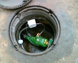
When looking at whole of life costs the primary maintenance item in the vacuum pump station are the vacuum pumps. Liquid ring pumps have lower ongoing costs but use a lot of water which can be expensive. Rotary vane Pumps require oil changes and filter changes and rebuilds are more common.

Discharge pumps in vacuum sewer systems have lower operational costs as they are a step removed  from risks commonly found with gravity sewer systems. Ragging and impacts from rocks are less common due to the collection tank location.

The vacuum interface valve has very few mechanical parts but will require a rebuild once every ten years on average. The parts required for this rebuild will cost less than $100 for each valve per rebuild.

To get a more detailed life cycle analysis of vacuum sewer systems, including their operational costs please contact your nearest Flovac office.

The Hidden Costs of Gravity Sewers versus Vacuum Sewers

When looking at what sewage infrastructure to use in a difficult area, most consultants will do a study which compares gravity sewers with vacuum sewer technology. In some smaller communities they may also do a comparison showing a low pressure or grinder pump system.

These costs are usually split between the Capital Cost of the Project and the Whole of Life costs. In some countries the consultant will also do a carbon footprint study to look at the environmental impact of the new infrastructure.

When looking at the Capital Cost for a sewerage infrastructure project engineers look at the following major items.

  • Pump Station Costs
  • Cost of Pipe in the Ground
  • Manholes or collection Pits
  • Property Connection costs to the Collection point
  • Rising Main Cost to the Treatment Plant

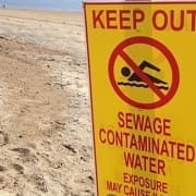
Will this information give a municipality or developer the full picture? What is being left off this analysis?

Pump Station Costs   – In a gravity system, multiple gravity pump stations may be required (up to 18) where one vacuum station will handle the flow. Is the cost of the land taken into account? How about the impact of a properties value if situated next to a gravity station?

Pipe Installation Cost – Usually the consultant will look at the price of pipe per metre installed in the ground, but how about how long the construction period is to install pipe in difficult ground where dewatering may be required. The gravity project in the photo  required 2 weeks per every 100 metres of pipe being laid. Some area’s with very hard rock may take longer. If dewatering what is the cost of disposing of the water? If requiring new fill from somewhere else to embed the pipe, what is that cost?

Impact on Community, Trade and House Sales. – If a project takes a long time to be installed then a municipality may not allow a developer to commence the sale of houses until all houses are connected to the sewer. If commercial area’s or shops cannot be accessed for extended periods this may have a financial impact on the project. If homeowners cannot access their homes then what is the political cost?

Easement Requirements – When looking at a low pressure pump scheme where pumps are required on private properties has the cost of an easement been built into the estimate? When looking at Whole of Life costs does it include washing down the sewage off people’s yards after repairs have been made to the pumps?

Treatment Plant Impact  – If designing a gravity sewer where infiltration will need to be accommodated will the Treatment Plant need to be upgraded and what is the impact of the increased  discharge?

Operational Costs and Risks. –  Health and Safety of operators, Odour, gas explosions, fatbergs, wet wipes clogging pumps, exfiltration damage. None of these are adequately covered in assessments.

Energy Costs – Does the community count the cost of the extra energy costs when it is only homeowners paying the cost with grinder pumps or do you need to look at the cost to the town. When infiltration occurs how much extra power will that consume at pump stations and at the treatment plant.

Increased Risk – is there an assessment given over possible EPA or environmental fines if a gravity system or low pressure system discharges sewerage into a sensitive area. What happens in a tourism area if the sewage overflows? How about in a fishery habitat?

There are many other hidden costs and many more long term costs to be taken into account, This is especially true when trying to repair a leak in a pipe 10 metres (30′) under the highway. I am sure you can think of other costs that have impacted on projects you have done in the past, If so, we would love to hear about your experiences.